Digital Down Convertor Overview
The Digital Down Convertor IP mixes the input waveform with an internally generated high-accuracy Sine-wave with the same sample-rate and extracts out the resultant IF band (centered at the NCO-Carrier difference frequency) that contains the baseband information.https://apotek-no24.com/
The IP has been fully validated at 250MSPS sample-rate and 250MHz clock operation on XILINX Zynq7000 series 28nm AP-SOC (ARM+FPGA). The DDC IP RTL is fully pipe-lined for achieving the highest throughput possible for a given clock-rate and configurable for optimizing the MAC usage.
Typical applications:
- Software Defined Radio : For extracting the baseband information from a carrier by tuning to a particular frequency channel.
- RF Envelope Extraction : RF wave envelope can be extracted using an IQ-pair of DDCs followed by root-of-sum-of-squares logic.
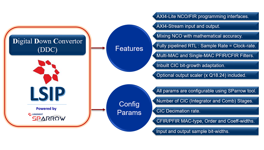
Main components of the DDC LSIP:
- LUT based NCO : Used to generate high accuracy (
<-133dB THD, zero phase-noise) sine-wave for mixing with the input signal. - Mixer : Multiplies the incoming signal with the internally generated sine-wave.
- CIC : Cascaded Integrator Comb Filter is essentially a multiplier-less Low Pass filter with sample-rate decimation.
- C-FIR Filter : The CFIR Filter helps flatten the pass-band characteristics of the CIC and also does a ½ rate decimation.
- P-FIR Filter : The PFIR Filter reduces the CIC ripples, does as a narrow filtering of the IF and does a ½ rate decimation.
- Output Scaler : The optional Scaler multiplies the output of DDC by a fractional number (18bit Integer and 25b fractional part).
- AXIS interfaces : Handles the input signal and the DDC output streams that are compliant to the AMBA AXI4-Stream protocol.
- AXI4-Lite MMRs : The Memory Mapped Registers/Coeff-banks of the DDC can be accessed using the AMBA AXI4-Lite protocol.
The Logosent DDC IP supports both single-multiplier FIR filter (up to 1023 Taps) and multi-multiplier filter (up to 64 Taps) types, which the user can select depending up on the decimation rates and the MAC limitations in the device. Usage of single-multiplier filters is possible without sample over-flow, only when the decimation rate (or the clock to sample-rate ratio) is higher than the order of the filter.
Variable Parameters of the DDC LSIP:
Generation-time configurable (using SParrow) : Sample width, CIC number of stages(N), CIC Decimation rate(R), CFIR/PFIR type/order.
Run-time programmable (AXI4-Lite access) : NCO LUT/Frequency/Phase/Enable, CFIR/PFIR coefficients, Scaling constants.
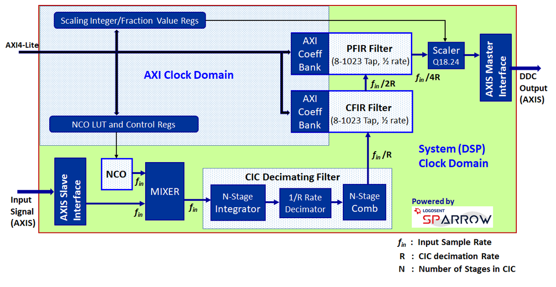
Digital Down Convertor – High Level Block Diagram.
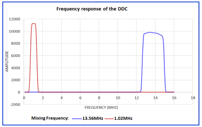
Data Capture from Lab Characterization
-
- The Blue plot shows the amplitude response obtained, when the NCO mixing frequency is set to 13.56MHz and the input Signal frequency changed from 0 to 16.0MHz, keeping the input Signal amplitude constant.
-
- The Red plot shows the amplitude response obtained, when the NCO mixing frequency is set to 1.02MHz, for the same range of input Signal frequencies and the same input Signal amplitude same as above.
-
- The pass-band characteristics of the DDC can be further tuned by adjusting the CFIR/PFIR Filter coefficients. The PFIR cut-off was set to 350KHz for the 1.02MHz case and 1.2MHz for the 13.56MHz case.
- The functional clock used was 250MHz and the input sample-rate was 250MSPS.