Envelop Extractor Overview
The Logosent Envelope Extractor IP combines the power of our high-accuracy NCOs, configurable DDCs and a fully pipe-lined Newton-Raphson square-root engine to extract the envelope waveform riding on the input signal. The NCOs can be tuned to the desired frequency so that, the envelope of any particular carrier frequency from a mixed channel input can be extracted out.
The CFIR/PFIR coefficients of the two DDCs are made programmable, in order to improve the accuracy of the channel selection. An optional decimator and anti-aliasing FIR filter combination is also provided at the output to facilitate bringing down the envelope output sample-rate to the desired levels.
The IP has been fully validated at 250MSPS sample-rate and 250MHz clock operation on XILINX Zynq7000 series 28nm AP-SOC (ARM+FPGA).
Typical applications:
- Demodulation : For extracting the baseband signal from a carrier by tuning to a particular carrier-frequency channel.
- RF Plasma generator : For monitoring the amplitude of pulsed/continuous RF waveforms used in plasma chambers.
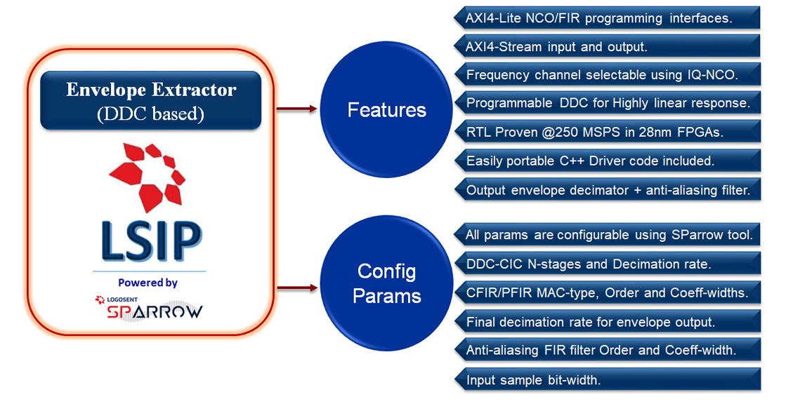
Main components of the Envelope Extractor LSIP:
- LLUT based IQ-NCO : Used to generate high accuracy ( <-133dB THD, zero phase-noise) Sine/Cosine-waves for mixing with the input signal.
- Two DDCs : Used to extract the complex (IQ) IF waveforms from the input signal.
- Root of Sum-of-Squares : The I and Q outputs of the two DDCs are fed to the root-of-sum-of-squares logic for computing the envelope output.
- Output Decimator : The decimator rate can be configured to achieve the desired sample rate for the output envelope waveform.
- Output FIR Filter : This low-pass FIR Filter is used along with the output decimator to filter out any aliasing effects of final decimation.
The DDCs in the Envelope Extractor LSIP supports both single-multiplier FIR filter (up to 1023 Taps) and multi-multiplier filter (up to 64 Taps) types, which the user can select depending up on the decimation rates and the MAC limitations in the device. Usage of single-multiplier filters is possible without sample over-flow, only when the decimation rate (or the clock to sample-rate ratio) is higher than the order of the filter.
Variable Parameters of the Envelope Extractor LSIP:
Generation-time configurable (using SParrow) : Sample width, CIC stages(N) and rate(R), CFIR/PFIR type/order, output decimation rate, output FIR order.
Run-time programmable (AXI4-Lite access) : NCO LUT/Frequency/Enable, DDC CFIR/PFIR coefficients, Output FIR coefficients.
Envelop Extractor – High Level Block Diagram.

Data Capture from Lab Characterization
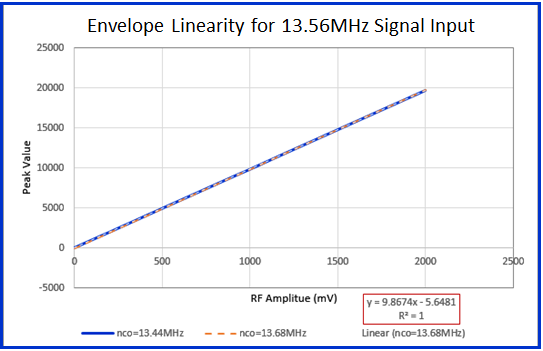
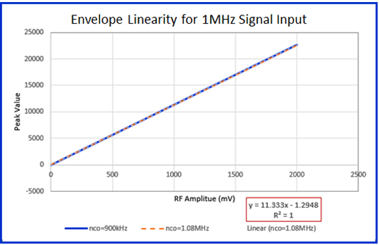
- Measurements were done on input Signal with 2V Peak-to-Peak Amplitude, captured at 250MSPS sample-rate.
- Input amplitude range 0mV to 100mV was measured at 10mV increments.
- Input amplitude range 100mV to 400mV was measured at 50mV increments.
- Input amplitude range 400mV to 1V was measured at 100mV increments.
- Above 1V Input amplitude range was measured at 200mV increments.
- The Envelope Detection Logic was operating at 250MHz.
- The scaling of the output and the pass-band characteristics can be tuned by choosing appropriate PFIR/CFIR Coefficients.